上海长春自控工程有限公司
地址:上海市徐汇区龙吴路410弄1号
E-mail:sh@021changchun.com
shccace@163.com
电话:+86 21 63845867
+86 21 63858705
传真:+86 21 63858705
网址:http://www.021changchun.com
邮编:200232
| XXS-99型微机信号报警系统说明书(中英文) / XXS-99 Computer Signal Alarming System 返 回 | |
1.概述 XXS-99型机柜式报警系统是用在大型发电机组运行中的越限报警和化工行业中防护报警。该系统充分利用了当代计算机的软件和硬件控制的特点来满足不同容量的要求和操作控制的要求,可广泛用于电力、化工、石油、冶金等场所,是确保各种设备与系统安全运行不可缺少的装置。 XXS-99型机柜式报警系统特点: 1.1.采用高性能的INTEL8031单片微机为控制核心,组成多微处理机的组件化系统,因而具有可靠性高、稳定性好、抗干扰性能强等优点。 1.2.机内均用标准化模块结构形式,来满足不同容量的要求,部件通用,扩展灵活,操作维护方便。 1.3.最适合于国内电力系统大型发电机组闪光音响报警需要。 1.4.为提高抗干扰能力,在硬件和软件上采用抗电网干扰的有效措施。如光电隔离、电源滤波器、屏蔽、程序一旦“飞”出去立即“飞”回等等。 1.5.可以为用户提供特定的控制程序固化EPROM2764。
2.主要技术指标 2.1.输入信号: 2.1.1.常闭、常开触点可任意混合选择,由报警单元插件板上双列直插式拨动开关选取。 2.1.2.均有光电隔离装置。 2.1.3.具有信号解除选择开关。 2.1.4.可再传输(返送)。 2.2.报警点数:160点。 2.3.现场触点电压:+24V(DC)、电流:7mA(由报警系统提供)。 2.4.操作控制按钮:“试验”、“确认”、“消音”、“复位”这四个按钮为一组,可以分组接到操作控制台。 2.5.指示设备:LED发光体光字牌。报警信号首出快闪,后续慢闪。 2.5.1.光字牌:每个光字牌尺寸:48mm×96mm、32mm×72mm、40mm×80mm三种。光字牌有红色、绿色、黄色等多种颜色,供用户按不同监控要求选用。 2.5.2.光字牌组合方式:可任意组合,见图4。 2.5.3.音响装置:电铃或蜂鸣器。常规音响和紧急音响。 2.6.稳压电源:微处理器用开关电源+5V/20A、信号触点用开关电源+24V/4.2A、光字牌灯用电源+24V/20A和监控单元用多路开关电源。 2.7.机柜外形尺寸:高2.1米,宽0.70米,深0.60米(特殊尺寸可定制)。 2.8.端子排和电缆: 2.8.1.输入信号端子排10块,每块16个信号触点。 2.8.2.信号输入电缆是从发电机组通过地沟进入机柜。光字牌连接(19芯)输出电缆可以从机柜底部引入机柜。电缆长度由用户确定。 2.9.整机功耗:正常使用不大于150瓦。 试验时小于760瓦。 2.10.环境温度:0℃~60℃ 。
3.微机报警系统结构和安装 XXS-99型微机报警系统为机柜结构,机柜尺寸为高2.1米,宽0.70米,深0.60米(特殊尺寸可订货时说明,另行定制)。机内各部分位置见图1、图2,其中图1为机柜前面视图,图2为机柜后面视图。
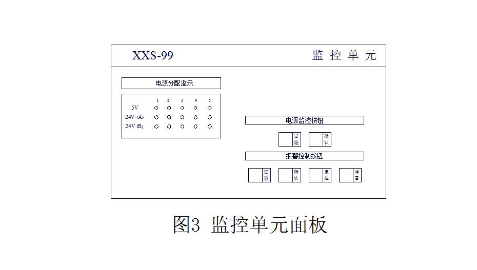
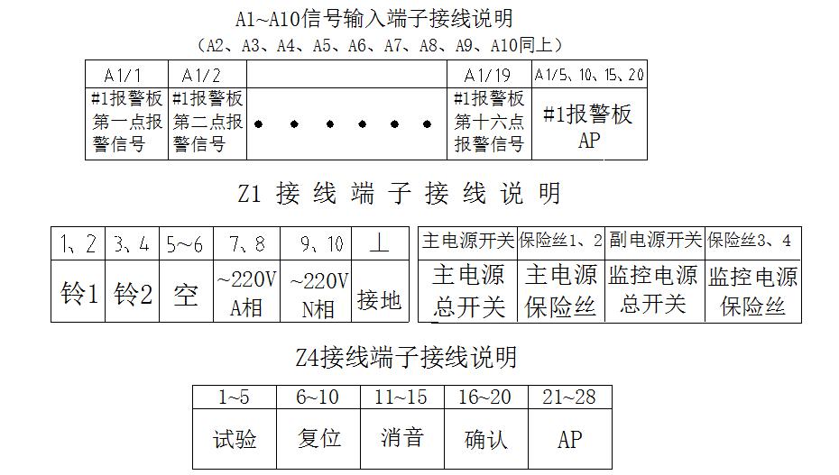
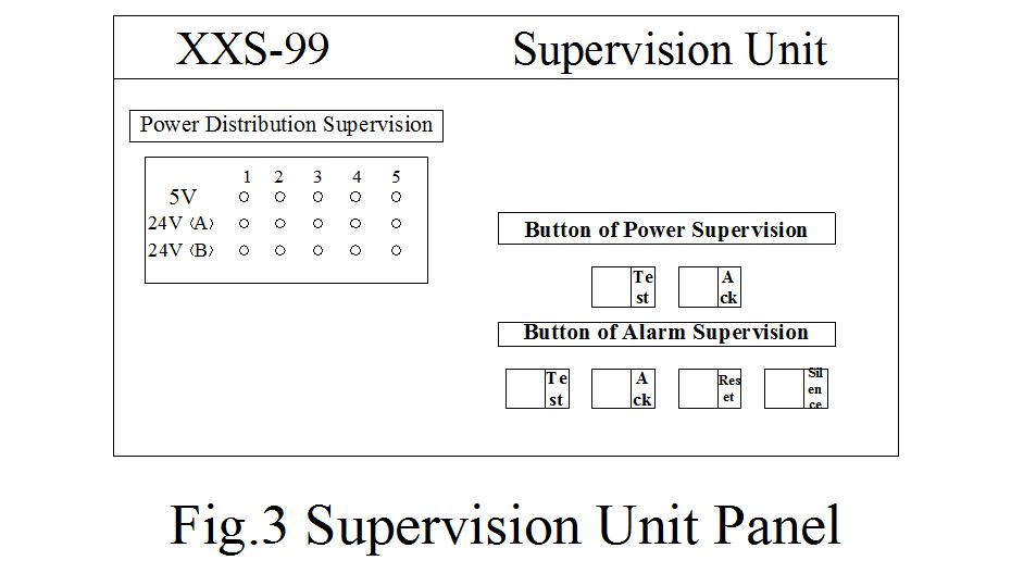
3.1.报警信号端子排 报警信号端子排如图2,位于柜子后面左右两侧,右边为A1~A5(80个)信号输入端子,左边为A6~A10(80个)信号输入端子。它与发电机组的报警接点通过电缆线接入微机报警单元的报警插件板。(接线端子排列及接线说明见附1、附2) 3.2.微机报警插件板 在图1的报警单元中可插10块报警插件板,每块报警插件板上有16个报警点,报警接点可以是常开接点,也可以是常闭接点。每块板均相同结构,可以互换替代使用。每块报警插件板上有四个发光管指示灯,作为工作指示。在运行时用,上端第一个LED发光管在正常工作时应常闪,其呈平光或不亮时,表示此报警板有故障,此时拔下故障板(可带电插拔),用新板换之。 3.3.监控单元 监控单元为整个报警系统监示和控制的核心。图3为监控单元面板视图,它的左边为“电源分配监示”,其中有十五个发光指示灯,分别表示5路3组电源(5V、24V(A)、24V(B))的工作状况,灯亮为该路该组电源发生故障。它的右边为控制按钮。
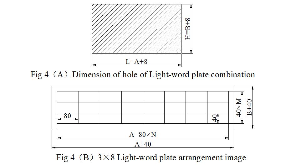
3.4.光字牌组: XXS-99型微机报警系统的光字牌是分组安装在盘上,每组以任意矩阵方式排列,例如6×6=36个、6×4=24个、8×3=24个等排列供选择,各自的开孔尺寸见图4所示,也可以根据现场要求另外排列。盘上每组光字牌通过配有N个19芯航空插头的电缆线接至报警单元的背面,与报警插件相接。
开孔尺寸计算:每个光字牌尺寸为:高×宽(mm)三种:48×96、40×80、32×72。 设N为横向光字牌数量,M为竖向光字牌数量,则光字牌屏外尺寸: 横向A=每个光字牌宽×N 竖向B=每个光字牌高×M 因此盘上安装开孔尺寸:横向L=A+8 竖向H=B+8 设光字牌屏边框为20mm,则光字牌屏外形尺寸:横向A+40,竖向B+40。 图4(A)为组装式光字牌安装开孔尺寸。 例如:组合8(横向)×3(竖向)光字牌排列,假如每个光字牌尺寸为40×80(mm),则开孔尺寸为:L=A+8=640+8=648(横向)、H=B+8=120+8=128(竖向)。 3.5.电源 系统配备三组直流电源:+5V、+24V(A)、+24(B),分别用于微处理器控制,光字牌LED供电及输入信号接点电压。三组电源通过电源分配总线(端子排引出)到各部分,当分配总线中的一路有故障时,机内自备电源立即进行监控指示。三组电源安装于机柜上部。隔离变压器安装在机柜底部。
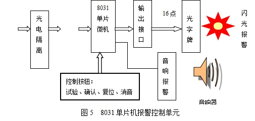
4.微机报警系统原理 报警系统是监视用户系统信号的装置,一旦发现用户系统异于平时正常信号时,报警系统报警。例如,平时某触点是常开的(或常闭),当监测到这对触点闭合(或断开)时,报警系统铃响,相应信号的光字牌闪光,提醒值班
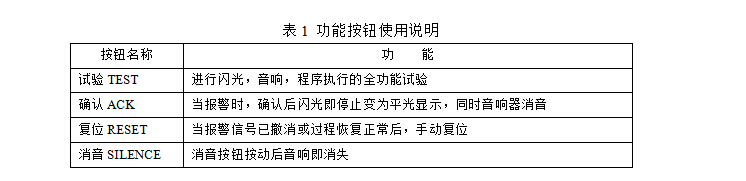
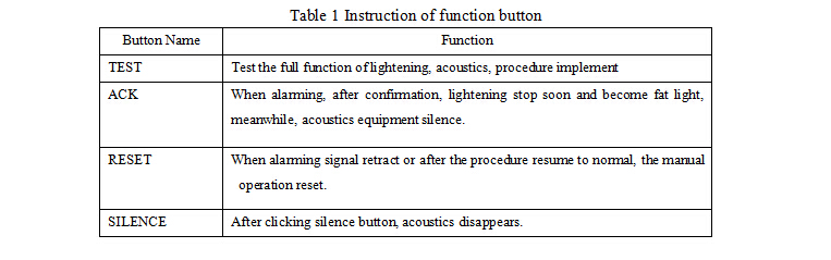
工作人员某处发生了故障,或开始了某过程,图5为报警单元结构框图。 图5中控制器采用8031微处理器,控制程序放在EPROM2764内。控制台为四个按钮:试验、确认、复位、消音。各按钮功能见表1。
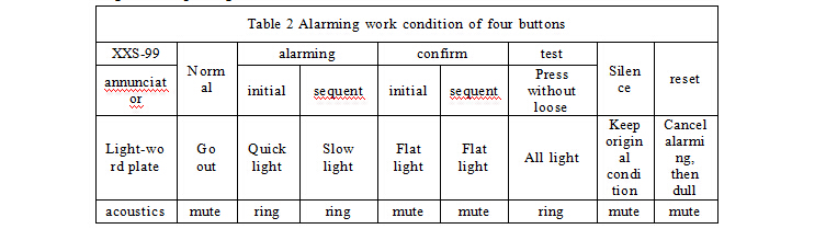
5.操作使用方法 5.1.开机和系统指示 当微机报警系统各部分安装连接完毕后,便可将机柜下方的总开关合上开机通电,通电后电源单元上电压表指示正常,监控单元面板上的15个电源分配总线故障指示灯均不亮,每个报警单元面板上第一个“闪光报警指示”应该闪光,这样表示整个系统内工作基本正常。 5.2.自检测试 报警系统可由监控单元面板上的试验按钮或盘上的试验按钮对160点报警通道进行自检测试,按下试验按钮时光字牌应闪光、音响报警,表示160点自检测试全部正常,可以投入使用。 5.3.报警控制按钮的操作 盘上的各组报警控制按钮中的“试验”“复位”、“确认”、“消音”电气上均是并接使用。 现场来的任何一个报警信号都能使对应的光字牌闪光且铃响。首出点快闪,后续点慢闪。当按动“确认”按钮后则闪光变为平光,同时音响消除,若接着又有新的报警信号则该点对应的光字牌闪光,且响铃。而已确认过的报警点继续保持平光,报警点撤消,对应光字牌熄灭。见表2。
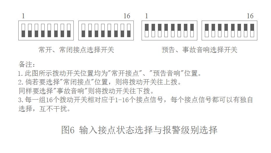
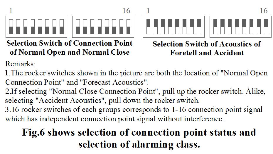
5.4.微机报警插件板 每一块报警插件板均为独立对16个报警点进行报警的控制单元,每块插件板的正面有四个指示灯,最上面的指示灯为同步闪光指示,其他三个灯亮分别表示微处理器、信号公共接点(AP)电压和光字牌公共电压正常。每块微机报警插件板可以在机内互换替代。 5.5.常闭、常开触点的混合选择 每块微机报警插件板的16个报警点,可以根据发电机组的常开、常闭接点进行混合选择。选择方法只要将报警插件板上的16个微型拨动开关按常闭、常开方向拨动即可。同样可选择“预告音响”与“事故音响”,见图6。
附1:接线端子排列图 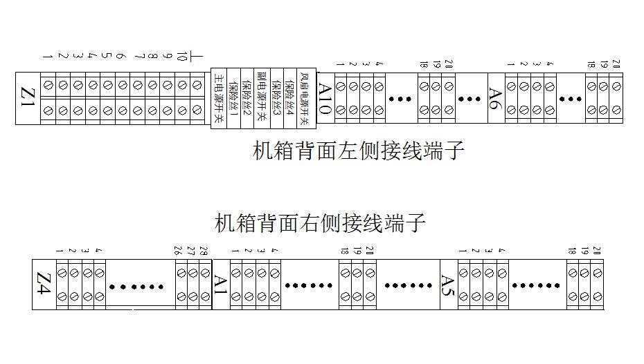
附2:接线端子接线说明
XXS-99 Computer Signal Alarming System
CONTENTS
1.Overview………………………………………9 2.Main Technique Index…………………………9 3.Structure and Installation of Computer Alarming System……………………………………………10 4.Theory of Computer Alarming System ………13 5.Method of Operation …………………………14 References: 1.Computer Signal Alarming System and Application(Wu Yinan) Shanghai《Automation Meters》88, 9th Period 2.XXS-87 Computer Signal Alarming Setup(Wu Yinan, Xu Zhenhai) Irrigation Electric Power Department《Electric Power Technology》 89, 2nd Period
1. Overview
XXS-99 Cabinet Type Alarming System is the threshold-crossing alarming in large dynamotor group and protection alarming in chemical industry. The system takes advantage of the characteristics of software and hardware control of contemporary era to meet the requirement of different capacity and operation control which can be widely used in electric power, chemical industry, petroleum, metallurgy and so on. It is the indispensable equipment guaranteeing secure operation of all equipments and system.Characteristics of XXS-99 Cabinet Alarming System: 1.1. Adopt high performance INTEL8031 single-chip computer as control core to group parent system of multiple microprocessor. It owns the advantages of high credibility, good stability, and strong anti-jamming ability. 1.2. Computer adopts the format of standard module structure to meet the requirement of different capacity with the advantages of universal parts, flexible expansion, easy operation and maintenance. 1.3. Available to the requirement of flash acoustics alarming of large dynamotor of electric power system. 1.4. In order to enhance the ability of anti-jamming, adopt effective measure of anti-jamming of electric network in hardware and software, such as optoelectrical separation, power supply filter, screen, once program “fly away” but “fly back” immediately. 1.5. Offer optoelectricaer users with special control procedure frozen EPROM2764.
2. Main Technique Index
2.1. Input Signal:2.1.1. The contact of normal close and normal open can be mixed selected a twill by rocker dual in-line package switch in the component board of alarming unit to select. 2.1.2. Have optoelectronic separation equipment 2.1.3. Have selection switch of signal unblock 2.1.4. Can be re-transmitted(return). 2.2. Alarming points: 160 points. 2.3. On-site contact voltage:+24V(DC)、current:7mA(offered by alarming system). 2.4. Button of operation control: four buttons of “test”, “confirm”, “silence”, “reset” is a group which can be grouped to contact to operation console. 2.5. Indication equipment: LED illuminant light-word plate. Alarming signal firstly quickly glitters and later slowly glitters. Initial alarming signal quickly lightens and sequent one slowly lightens. 2.5.1.Light-word plate: dimension of each light-word plate: three kinds of 48mm×96mm、32mm×72mm、40mm×80mm. The light-word plate has color of red, green, yellow and so on which can be selected according to different supervision by users. 2.5.2. Combination mode of light-word plate: random combination, see fig.4. 2.5.3.Acoustics Equipment: ringing or buzzer. Normal acoustics and emergency acoustics. 2.6. Stable voltage power: Microprocessor uses+5V/20A switch power, signal contact uses +24V/4.2A, light-word plate uses +24V/20A and supervision unit uses multiple switch power. 2.7. External dimension of cabinet: 2.1 meters in height, 0.70 meters in width, 0.60 meters in depth (special dimension can be customized.) 2.8. Terminal socket and cable: 2.8.1. Input signal terminal socket 10 blocks and each block has 16 signal contacts. 2.8.2. Signal input cable enters cabinet via ground groove by dynamotor group. Light-word plate connects output cable (19 chips) which can induct to cabinet from the bottom of cabinet. The length of cable is decided by users. 2.9. Integrated consumption: not more than 150 watt in normal application and less than 760 watt in test. 2.10.Enviroment temperature: 0℃~60℃.
3. Structure and Installation of Computer Alarming System
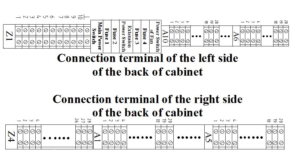
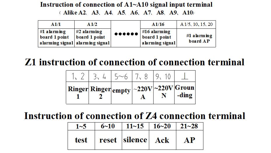
XXS-99 computer alarming system is cabinet structure. The dimension of cabinet is 2.1 meters in height, 0.70 meters in width and 0.60 meters in depth (special dimension can be instructed when ordered and can be customized). The location of each part in the interior of cabinet can be seen in fig.1, fig2, among which fig.1 is cabinet front view and fig.2 is cabinet back view. 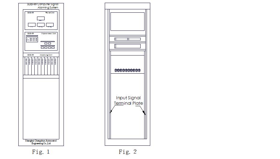 3.1. Terminal Socket Alarming Signal Terminal socket alarming signal is shown as fig.2 which is in the two side of right and left in the back of cabinet. The right is A1~A5 (80) signal input terminal. The left is A6~A10 (80) signal input terminal. It access alarming parts board of computer alarm unit with dynamotor group’s alarming contact via cable. (see appendix 1 and appendix 2 for connector terminal arrangement and connector instruction). 3.2. Parts Board of computer alarming In the alarming unit of fig.1, 10blocks of alarming parts board can be inserted. There are 10 alarming points in each alarming parts board. Alarming contact can be normal open contact and normal close contact. Each board has the same structure and interactively substituted to use. Each alarming parts board has four light emitting diode indicator light which is job instruction. When it is in operation, the first LED light emitting diode in the upper end is normal lightening in normal work. When it is fat light or dull, it means that the alarming board has failure. At that time, pull out failure board (can plug-in with power) and change with new board. 3.3. Supervision Unit Supervision unit is the supervision and control core of the whole alarming system. Fig.3 is panel view of supervision unit. Its left is “power distribution supervision”, among which there are 15 light indicator light respective showing the work condition of the power of 5 lines 3 groups (5V,24V(A),24V(B). lightening means failure happening in the power in the group. Its right is control button.
4. Theory of Computer Alarming System
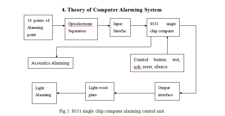 Fig.5: 8031 single chip computer alarming control unit Alarming system is the equipment to supervise users’ system signal. Once users’ system is found to be different from normal signal, the alarming system will alarm. For example, certain contact in usual time is normal open (or normal close). Whenthe contact is found in close (or cut down), alarming system will ring and corresponding light-word plate will flash to remind personnel in charge of failure eeng. Or begin certain process. Fig. 5 is the structure image of alarming unit. The controller in fig.5 adopts 8031 microprocessor and the control program is put in EPROM2764. The console is four buttons: test, ack, reset, silence. See function of each button in Table.1.
5. Methods of Operation
5.1. Start-up and System IndicationAfter the completion of the installation and connection of each part of micro computer alarming system, the general switch below the cabinet closes to start-up and electrify. After electrified, the voltage table in power unit indicates normal. The failure indicator of 15 power distribution in supervision unit panel is dull. The first “Light Alarming Indication” in each alarming unit panel shall light which shows the normal work of the whole system. 5.2. Self-test Alarming system can self-test 160 alarming channel by the test button in supervision unit panel and the test button in panel. When pressing test button, light-word plate shall lightening and acoustics alarms showing that 160 self-test are normal and can be exerted to use. 5.3. Operation of Alarming Control Button Then button of alarming control of each group in plate of “test”, “reset”, “confirm” and “silence” are combined to use. Any on-site alarming signal can make corresponding light-word plate lighten and ring. The initial point lightens quickly and sequent point lightens slowly. When pressing the button of “confirm”, the light becomes flat light and meanwhile acoustics is silent. If there is new alarming signal, the corresponding light-word plate lightens and rings. The confirmed alarming point continues to keep flat light and alarming point retracts as well as corresponding light-word plate goes out. See table 2.
|